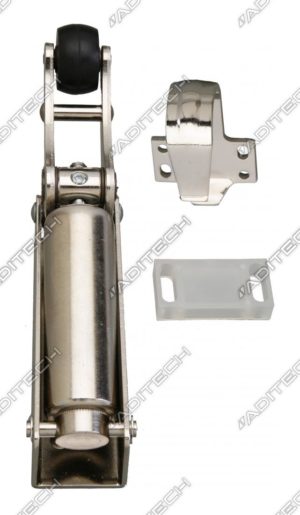
Door check

| Version | Closing force | Article-Nr. |
|---|---|---|
| With final latch. | 30 N | 13335035 |
| With final latch. | 40 N | 13345035 |
| With final latch. | 60 N | 13365035 |
| Closing speed is adjustable. | ||
| Surface nickel plated. |
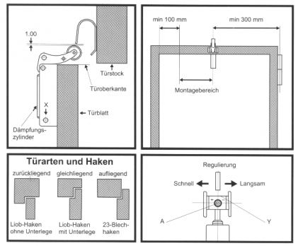
For right and left doors the same modell will be used, furthermore distinguished between 3 kinds of doors: overlying, backlying, samelying.
Installation instruction
- Door closers are usually mounted in the middle of the door. When assembling on the strike plate side, the distance
 to the door edge may not fall below 115 mm.
 - To mount the lock box the foot bolt must be removed. Then the cylinder can be fold out to expose the mounting holes. Subsequently adjust the shutter box with the result that the top is 1 mm higher than the top of the door. Fix it with bolts in the middle of the elongated holes.
- Insert the foot bolt and check the function of the closers manually.
- Adjust the hook on the frame so that the rubber roller enters the upper nib (closer must be tensed), then mark the middle of the elongated holes and fix it with bolts.
- Now perform a function check. The assembling measure amounts ca. 90 mm. If all functions are impeccable, finally you can fix the hook and the closer in the elongated holes and push the lock washer on the foot bolt.
- The lock speed can be adjusted by using a hex driver in a rotary range of 270°. Before then the clamp screw must be unloosed and after the adjustment she must be fixed. Door closers with an adjustment inside the piston rod you can adjust the lock speed by turn the regulation screw in right way to slow down and by turn it in left way to accelerate.
